KYON AIRCRAFT · IN PROCESS
Same speed class, same station, without a pilot in the seat.
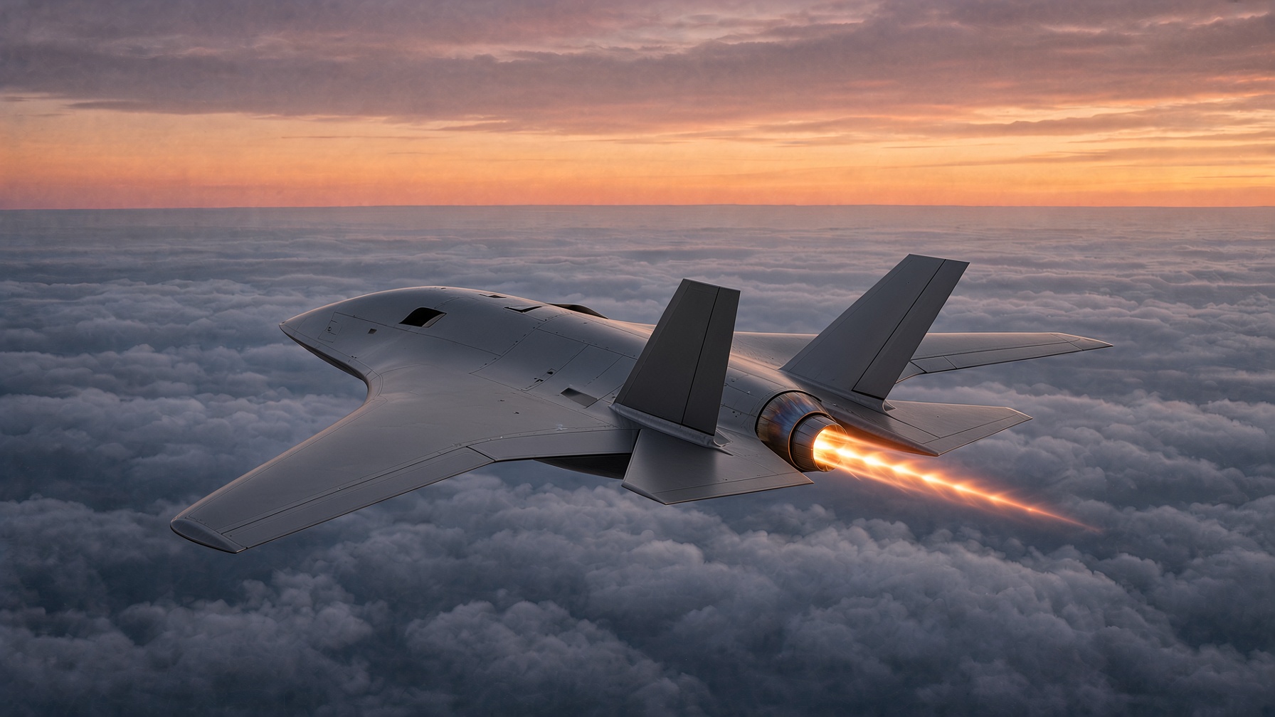
Carbon-fiber BMI composite for the skins. Titanium where the heat and the torque live: the engine bay, the nozzle, the wing roots, and the mounts. Aluminum-lithium in the cooler structure, where the load is real and the heat is not. A radar-absorbent coat over the outside, not a bare weave. The panels sit on the structure lines. Edges are tight, fasteners are flush, and the coat covers the seams so the shell reads as one surface. Twin canted tails. It flies alongside other fighter jets and carries a similar payload. Same speed class, same station, without a pilot in the seat.
Public description of a Kyon Dynamics aircraft. It is not a fielding statement, a performance claim, or controlled technical data. Released dimensions stay with the build, not on this page. The drawing board below is the same article as the live picture: same gear, same tails, same nozzle, same wing.
LINE PLATE · MERIDIAN · SIDE · PLAN · FRONT
IN PROCESS
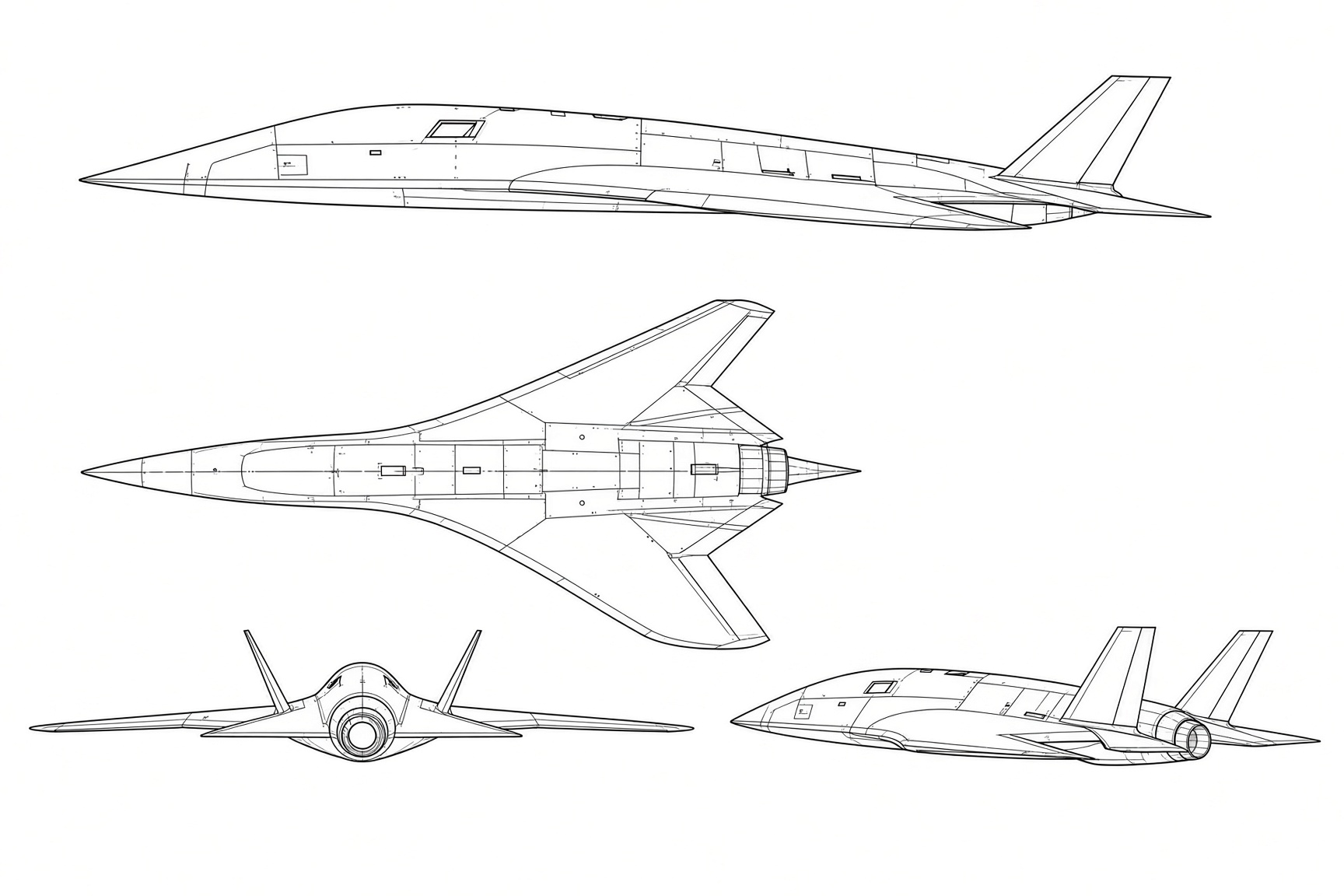
LINE PLATE · MERIDIAN · SIDE · PLAN · FRONT
KYON DYNAMICS INC.
Meridian
Same speed class, same station, without a pilot in the seat.
NTS · FOUR VIEWS · NOT RELEASED
Sheet
Side, plan, front, and a three-quarter, on one sheet. Same article as the live picture. Not a released drawing.
- Skins
- Carbon-fiber BMI composite
- Hot section
- Titanium — engine bay, nozzle, wing roots, mounts
- Cool structure
- Aluminum-lithium, where the load is real and the heat is not
- Coat
- Radar-absorbent coat over the outside, not a bare weave
- Empennage
- Twin canted tails
- Station
- Alongside other fighter jets, similar payload, no pilot in the seat
- Build
- In process
D5 layers in this model
Structure
Aluminum-lithium in the cooler structure. Panels sit on the structure lines.
Materials
BMI skins, and titanium where the heat and the torque live.
Systems
Engine bay, nozzle, and the mounts.
Signature
Radar-absorbent coat. Flush fasteners. The shell reads as one surface.
How the article is being built
One floor. Six disciplines.
One floor. Six disciplines. Nothing is farmed out that the building can do itself. Paint and metalwork sit beside the six. They are not a seventh product line.
Design & Engineering
Surface models, inner structure, and the analysis that says a part is light enough and strong enough before anyone cuts a tool.
- CATIA V5 and SolidWorks
- Autodesk Alias, sketches, and renderings
- Finite element analysis
- Surfacing and tooling design
- Manufacturing feasibility
- 3D printed studies before the metal tool
Laser Scanning
A tracker on the part, not a guess in the model. Edges, spars, and tools get measured where they actually sit.
Reverse Engineering
Customer models arrive unfinished. The scan is closed into surfaces the floor can tool.
5-Axis Programming & Machining
Bulkheads, hard points, molds, and fixtures. Programmed on that floor, cut on that floor, in metals, plastics, composites, foam, and tooling board.
Composite Tooling
The mold is the part’s first assembly fixture. Soft tools, production molds, and tooling sets leave that floor, not a subcontractor’s.
Composite Parts
Wet layup and prepreg. Skins, spars, radomes, fuselage elements, and the repair when an article comes back.
Floor support, not a seventh line: Large downdraft paint booth, color match, and aerospace finishes. MIG, TIG, plasma, shear, slip roll, and brake. Large surface plates.